Wiring Diagrams and Installation Essentials for Motors and Controllers #
This page provides a comprehensive collection of wiring diagrams for motors and brakes, designed to support your technical needs. Please ensure you follow the provided diagrams and consult the operation manual before using any motors to prevent potential damage.
Installation Preparation #
Before installing any motor, please observe the following guidelines:
- Confirm that the correct voltage is available for the motor prior to installation.
- Verify the model, model number, output, shaft direction, gear ratio, and direction of rotation to ensure they meet your requirements.
- Avoid bending the lead wires during installation.
- Only trained technicians should perform the installation process.
- Always refer to the appropriate wiring diagram when equipping motors.
Wiring Diagrams for K-Series Motors #
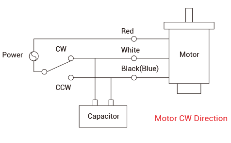
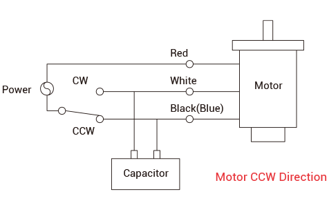
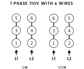
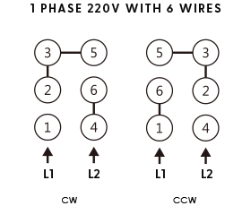
Single-Phase Motor Wiring #
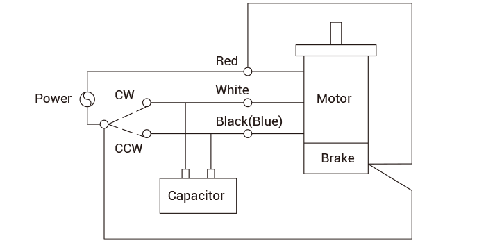
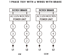
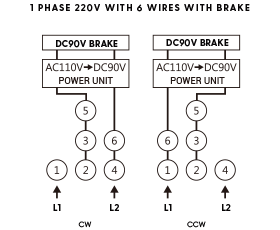
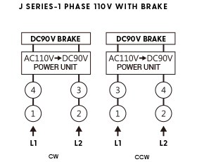
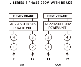
Single-Phase Brake Motor Wiring #
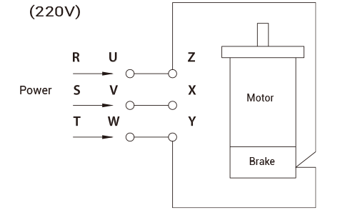
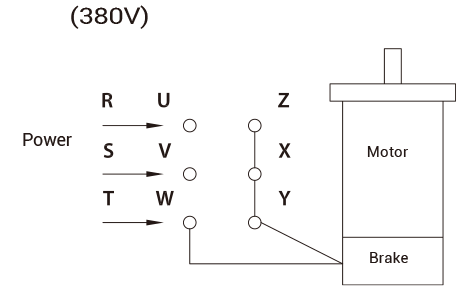
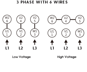
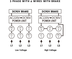
3-Phase Brake Motor Wiring (6 Wires) #
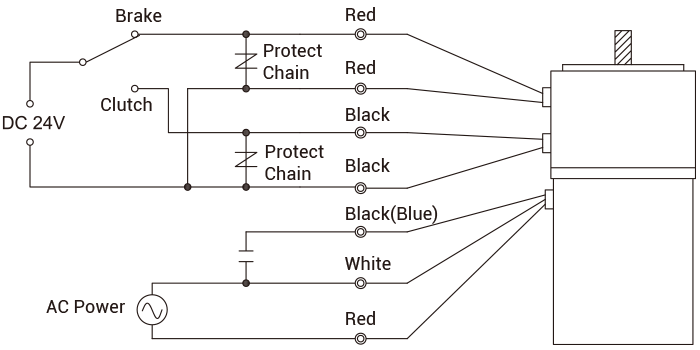
Clutch Brake Motor Wiring #
Wiring Diagrams for L-Series Motors #
Controller Wiring Diagrams #
SS11 / SS22 Controllers #
SB31-IN / SB32-IN Controllers #
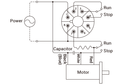
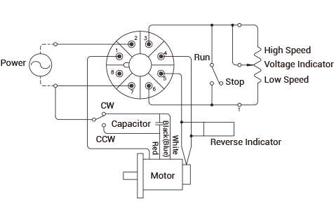
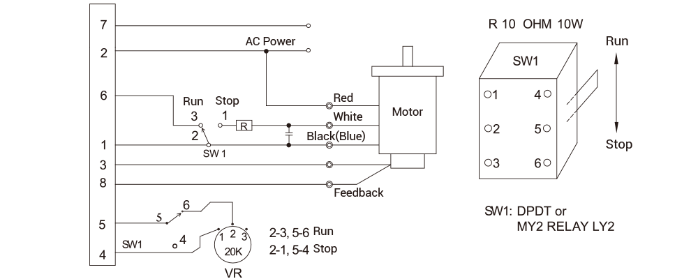
SS31-HR / SS32-HR (8PIN) Controllers #
- Pins 3, 8, 5, and 4 are for signal input. Please check carefully before applying AC power.
For further details, always refer to the operation manual and consult with technical support if needed.