Essential Motor Concepts and Selection Guidelines
Table of Contents
Essential Motor Concepts and Selection Guidelines #
This guide provides a clear overview of fundamental motor terminology and practical calculation methods, supporting informed decisions when selecting motors and speed reducers for diverse applications.
Motor Terminology #
Rating #
The rating defines the operational limits of a motor, including output power, voltage, current, frequency, torque, and rpm. Regarding temperature rise, ratings are categorized as either continuous or short-period.
Synchronous RPM #
The synchronous speed of a motor is determined by its frequency and the number of poles. The formula is:
- Ns = (120 × f) / P
- Ns: Synchronous rpm (revolutions per minute)
- 120: Constant
- f: Frequency
- P: Number of poles
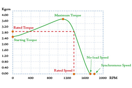
Rated Torque #
Rated torque is the torque produced by the motor at its rated rpm.
No-Load RPM #
This is the rpm of the motor when operating without any load.
Continuous and Short-Period Ratings #
- Continuous rating: The motor operates continuously at its rated output.
- Short-period rating: The motor runs at rated output for a specified, limited period.
Output Power #
Output power indicates the work a motor can perform per unit time, determined by rpm and torque. The formula is:
- Output (kW) = (T × N) / 97400
- T: Torque (Kgcm)
- N: RPM
- 1 HP = 0.746 kW
Starting Torque #
Starting torque is the instantaneous torque generated when the motor starts. If the load exceeds this value, the motor will not start.
Slip #
Slip is a measure of the difference between synchronous and actual rpm:
- S = (Ns - N) / Ns
- S: Slip
- Ns: Synchronous rpm
- N: Actual rpm under load
Motor Selection and Calculation #
Speed Reducer Series Overview #
Calculating Reduction Gear Ratio #
Select the appropriate reduction gear ratio to match the output rpm of the gear reducer with the operating machine’s requirements:
- i = Nm / Ng or 1 / i = Ng / Nm
- i: Gear ratio
- Ng: Output speed of gear reducer (rpm)
- Nm: Motor running speed (rpm)
Torque Calculation for Direct Link Speed Reducer #
Choose the model that matches the required output torque:
- Tg = Tm × i × η
- Tg: Reducer output torque
- Tm: Motor output torque
- i: Ratio
- η: Speed reducer transmission efficiency
Maximum Permissible Torque #
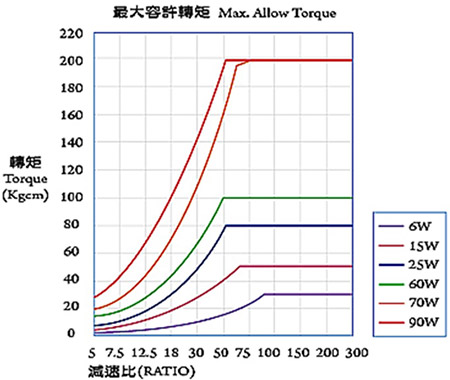
The output torque of a speed reducer is limited by the gearbox’s quality and structural design, especially at higher reduction ratios. Each model has a maximum permissible torque, as illustrated above.
Basic Motor Capacity Calculations #
General Formula #
- Pg = (P1 + P2 + P3) × 100 / η [W]
- P1 = 9.8 × μ × W × V × λ [W]
- P2 = (μ × Q × λ) / 367 [W]
- P3 = ± (Q × H) / 367 [W]
- λ: Conveyor length (distance between shafts, m)
- W: Weight per unit length of belt (kg/m)
- μ: Friction coefficient
- V: Belt speed (m/sec)
- Q: Conveyance volume (kg/h)
- η: Efficiency (%)
- H: Height difference between conveyor ends (m)
Lifting Load Applications #
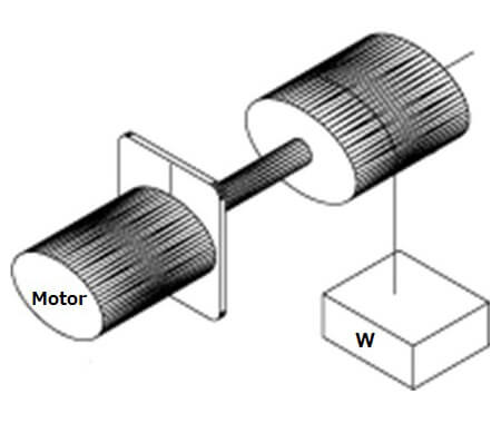
- Pg = (W × V) / (6 × 12) × (100/η) [W]
Driving Inertia Body #
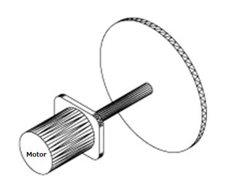
- Pg = 1.027 × N × T [W]
- T ≈ (GD² / 375) × (N / t) [kgf × m]
- N: Revolutions per minute (rpm)
- T: Torque (kgf × m)
- GD²: Flywheel effect (kgf × m²), including rotor
- t: Starting time (sec)
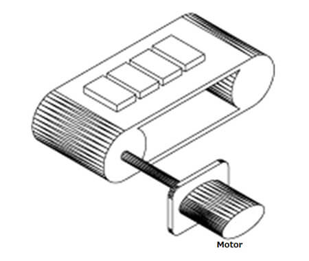
Level Movement on Contact Surface #
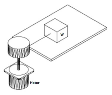
- Pg = (μ × W × V) / (6 × 12) [W]
For further assistance or detailed product information, please refer to the Technology Support section or contact our team.